E-mail: cysi@cysi.wang


The dicing and cutting machine uses a rotating cutting blade to slice large materials into smaller pieces of specified dimensions along predetermined lines (typically controlled by laser or computer). During the cutting process, the material is placed on a cutting table, and the blade's position relative to the material is precisely controlled to ensure each cut is accurate and flawless.

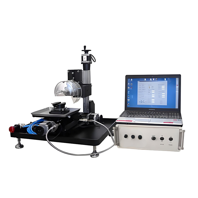
The CY-800 CNC Dicing and Cutting Machine is a computer-controlled 3D continuous cutting system, programmed via software to manage the cutting process. It is primarily designed for dicing and slotting materials such as crystals, ceramics, glass, and various thin materials. It can also cut other materials, including crystals, ceramics, glass, ores, and metals. The machine supports samples with diameters up to 200mm and cutting depths of up to 10mm.
The CY-800 employs a stepper motor drive, achieving a cutting accuracy of up to 0.02mm. Its sample stage features a vacuum suction cup that can rotate 360°. The spindle speed is adjustable and controlled steplessly, enabling fast cutting, smooth operation, and precise feed control. During operation, an external water circulation system can be connected to cool the sample, preventing damage or structural changes caused by heat generated during cutting. Depending on the material, different cutting blades can be selected. Additionally, the sample cutting table is equipped with a waterproof cover to prevent water splashes.
This machine is an ideal precision cutting solution for laboratories and production facilities processing large crystal wafers.
Computer Control: Operates using MTICUT software on a Windows OS, allowing users to program custom cutting processes.
Spindle Motor: Equipped with a 3000-rpm high-torque AC brushless motor, with adjustable speeds ranging from 0 to 3000 rpm via a speed control knob.
Rotary Table: Offers manual or automated 360° horizontal rotation with a tolerance of ±0.02°, ensuring easy and precise operation.
Vacuum Chuck: Features an 8-inch precision vacuum chuck, supporting wafers up to 200mm in diameter. During cutting, it uses a Ø220mm sample holder with a cutting range of 200mm x 200mm.
Customizable Blades: Compatible with different blades and spacers based on material size and requirements.
If you are interested in our dicing and cutting machine, feel free to contact us for more details and pricing.
Phone: +86 18516380382
Email: Jimmy@cysitech.com
Contact: Jimmy Hao
WeChat: +86 18516380382
WhatsApp: +86 13939946898
Parameter name | Parameter description |
Product name | Dicing machine |
Product model | CY-800 |
Working voltage | AC220V, 50Hz |
Spindle speed | 0-3000rpm stepless speed regulation |
Spindle drive power | 180W |
X-axis slide stroke | 200mm |
Y-axis slide stroke | 100mm |
Z-axis slide stroke | 55mm |
Processable dicing depth | 1.3mm |
Maximum cutting depth | 10mm |
X/Y/Z-axis drive motor | High-precision stepper motor |
Stepper motor positioning accuracy | 0.01mm |
Worktable rotation angle and error | 360°±0.02° |
Carrier plate diameter | Glass, Ø220mm |
Vacuum suction cup diameter | Ø203.2mm (8 inches) |
Saw blade size | Ø100/Ø150mm×Ø12.7mm (inner diameter installation size) |
Host control method | Computer version: computer program (USB) + single board computer |
Part name | Component Description |
Spindle | Support and rotate the cutting blade |
Cutting blade | The core component of the dicing machine, responsible for precision cutting of wafers or other materials |
Cutting table | Support and position the material to be cut |
Cooling system | Reduce the heat generated during the cutting process and reduce the wear of the blade |
Control system | Schedule and coordinate the work of various components |
Protective device | Ensure the safety of the operator |
Random accessories | Clamp, diamond saw blade, paraffin stick, waterproof cover, goggles |
User manual | Standard |
Semiconductor Industry: Used for dicing semiconductor wafers into individual chips from larger wafers.
Solar Panels: Cutting solar panels to meet different size requirements.
Electronic Component Manufacturing: For cutting various small electronic components, such as sensors and LEDs.
Optical Component Processing: Precision cutting of optical materials like laser glass and lenses.
Application Example: "Dicing a 6-Inch Wafer Using a Dicing and Cutting Machine"
1. Wafer Preparation
Cleaning: Thoroughly clean the 6-inch wafer before cutting to remove dust, impurities, and any substances that may affect the cutting quality. Common cleaning methods include ultrasonic cleaning and chemical cleaning.
Inspection: Check the wafer for visible defects (e.g., cracks or scratches) to ensure the material quality meets cutting requirements.
2. Positioning and Installation
Wafer Installation: Place the cleaned wafer on the dicing machine’s cutting table, typically secured using a vacuum suction system to prevent movement during cutting.
Precise Alignment: Use an automatic alignment system or laser positioning device to ensure accurate alignment of the wafer. Proper alignment is crucial to ensure that chip positions match the design specifications during the cutting process.
3. Cutting Plan Design
Path Setting: Use computer-aided design (CAD) software or the dicing machine’s control system to plan the cutting path. The path is optimized based on the wafer design requirements, including chip size, spacing, and cutting sequence.
Parameter Configuration: Set cutting parameters such as cutting speed, depth, blade type, and coolant flow rate to ensure quality and efficiency.
4. Blade Selection and Installation
Blade Selection: Choose a suitable blade, such as a diamond blade or another hard-material blade. Diamond blades are often used for semiconductor wafers due to their high hardness, ensuring cutting precision and quality.
Blade Installation: Mount the cutting blade onto the dicing machine’s spindle, ensuring it is securely installed for high-speed rotation.
5. Cutting Process
Start Cutting: Once all settings are complete, start the dicing machine. The blade rotates at the preset speed and cuts along the predefined path.
Depth Control: Adjust the blade’s cutting depth based on the wafer thickness, typically 50%-70% of the wafer’s thickness, to ensure smooth cutting.
Cooling System: Use coolant (usually water or water-based coolant) to spray onto the cutting area during the process. This reduces heat generation and minimizes blade wear.
6. Post-Cutting Processing
Quality Inspection: Perform an initial inspection of the diced chips to ensure cutting quality. Check for chip dimensions, edge smoothness, cracks, and burrs.
Cleaning: Clean the wafer and chips again to remove debris and coolant residues from the cutting process.
Drying: Dry the cleaned wafer and chips to avoid moisture affecting subsequent processes.
7. Follow-Up Processes (Optional)
Packaging and Storage: Diced chips are typically packaged to prevent damage or contamination. Packaging can range from encapsulated chips to bare die packaging.
Testing and Sorting: Some chips may undergo testing to ensure their electrical performance meets requirements. Chips that fail testing are sorted and discarded.
8. Quality Control and Recordkeeping
Quality Inspection: Conduct comprehensive quality checks on diced chips, including dimensional accuracy, surface quality, and electrical performance.
Documentation and Traceability: Record cutting parameters, quality control data, and product inspection results for future traceability and quality management.
Cutting Speed and Pressure: Avoid excessive cutting speed to prevent surface or edge cracks on the wafer. Control the cutting pressure carefully to ensure smooth cutting.
Coolant Flow Rate: Maintain sufficient coolant flow to reduce heat generation and prevent thermal damage to the wafer.
Blade Wear: Regularly inspect blade wear and replace blades as needed to maintain cutting precision and efficiency.
Chip Spacing: Precisely control the spacing between chips during cutting. Excessive spacing wastes wafer material, while insufficient spacing may lead to weak connections between chips.


Copyright © Zhengzhou CY Scientific Instrument Co., Ltd. All Rights Reserved Update cookies preferences
| Sitemap | Technical Support: 


